Mechanical Data Ø 0.45m High Performance Low Profile Antennas (HPL).
MATERIAL AND TREATMENT.
The reflector is made of aluminium and painted dark grey (RAL7302). All screws, nuts and washers are made of stainless steel A4 or hot dip galvanised steel class 8.8.
The antenna is protected with a low loss white hardcover radome.
A gear adjustment arrangement made of aluminium is used for accurate alignment. All screws, nuts and washers are made of stainless steel A4 or hot dip galvanised steel class 8.8.
The feed is made hot dip brazed aluminium. Further information is given in data-sheet for actual frequency range. The feed horn is sealed for pressurisation. A smooth continuous polarisation adjustment may be performed. The feed unit is made of hot dip brazed aluminium.
WEIGHT AND DIMENSIONS.
Dimentions acording to fig. 1.
Figure 1
Weight:
Antenna: 3.5 kg
Mount:7.0 kg
Antenna and Mount:10.5 kg
INTERFACE:
The gear adjustment arrangement may be installed to a 60 to 115 mm vertical column with minimum free length of 250 mm (not included). The antenna may alternatively be mounted to a vertical wall, just using four expansion bolts. (Not included.)The reflector is prepared for direct integration with all Nera radio outdoor units.
ALIGNMENT:
Coarse:Azimuth+ 360o, depending on column installations
Fine, both planes: From +15o to+180o, depending on column installations
ENVIRONMENT:
Wind
Survival without permanent deformation.
Wind speed up to 70 m/s and 25 mm radial ice.
Maximum deflection at 30 m/s is 0.1 o.
Temperature range:
- 55o C to + 55o C
Atmosphere:
The antenna is designed to meet coastal and industrial atmosphere with 100% relative humidity.
Wind load:
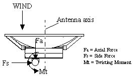
Wind effect on parabolic antennas and support structures can be separated into two force components and a twisting moment as shown in figure 2.
The side axial and twisting moment forces shown in table 1 are maximum values exerted on the supporting structure. In every case the value is the result of the wind from the most critical direction. All forces are referenced to the antenna-mounting column.
Table 1 : Wind force
Wind speed
Axial force Maximum N ( kp)
Side forceMaximum N ( kp)
Twisting moment Maximum Nm (kpm)
55 m/s (200 km/h)
553 (56)
248 (25)
220 (22)
70 m/s (252 km/h)
895 (91)
401 (41)
356 (36)
OREDRING
Antenna:According to frequency
PACKING
Nera HP Low profile antennas are packed as standard in totally recyclable cardboard packaging. The antenna is packed in two boxes, one for the gear adjustment arm and one for the reflector assembly. Interface kit is packed together with the adjustment arm.